Description
Inspired by the NeoGeo watch featured in Make magazine, I set out to create my own Arduino powered watch. Watches are boring though, and I didn’t see much need for a gps and compass in everyday use. Instead, I focused on making something that could help me instead of being a nuisance. Normal smartwatches, while a cool concept, are too expensive and generally lack any sort of customization. My goal was to build a watch that fell between the niche fitness trackers and full blown smartwatches. Using data sent by my phone, the Neopixel watch can display any notification, incoming calls, and precise time. It also features a timer with stop/start/reset, a calibrated uv brightness meter, a flashlight, and an auto-brightness function. Still in progress is an IR remote signal receiver and blaster, and music playback control using the button on the watch.
Feature Demo
Components
- Pro Trinket 3v/12mhz
- NeoPixel Ring 12x
- HC-06 Bluetooth Module
- SI1145 UV / Visible / IR sensor
- 650mah Lipo Battery
- USB Lipo Charger
- Slim Tactile Switch
- Vibration motor
Project Logs
01/16/2015
Initial Testing with Flora
This project was initially only supposed to be an Adafruit Flora with a band of neopixels strapped on the back. There are a few problems with this approach though. Firstly, the flora can’t keep track of time when it’s off. The NeoGeo watch solves this by locking to gps satellites to get the current time. Without any external source, the board would have to be reprogrammed on the fly, or have a method of setting the time via button input. Secondly, the clock on the atmel328 chip is not all that accurate. This can be solved by adding extra hardware, but I didn’t have the space for that.
Instead, I decided to connect the flora to my phone. This allowed the watch to always display the precise time nearly immediately when turned on and maintain the correct time, no matter how long it stayed on. It also unlocked a huge range of potential uses for the watch to interact with data from my phone.
01/18/2015
Flora + Neopixel woes
Had a bit of a rough start when testing some example sketches with the neopixel ring. After about a minute, the signal starts experiencing interference and the lights flicker and go white. I noticed that the chip on the flora was getting very hot as well. Putting my finger on the chip to draw heat away would stop the flickering, and a few seconds after removing my finger the flickering would start again. Weird. Neopixels don’t like when the data and Vin voltages are far apart, and I figured that the 3.3v logic and 5v Vin may have been causing issues, but even when connected to a LiPo I had the same issues. Re-soldering and using different wires had no effect either. In the end, I think it was the Flora. I also had issues with the board not reading any analog or digital inputs on any pin but D9.
02/03/2015
Adding Bluetooth
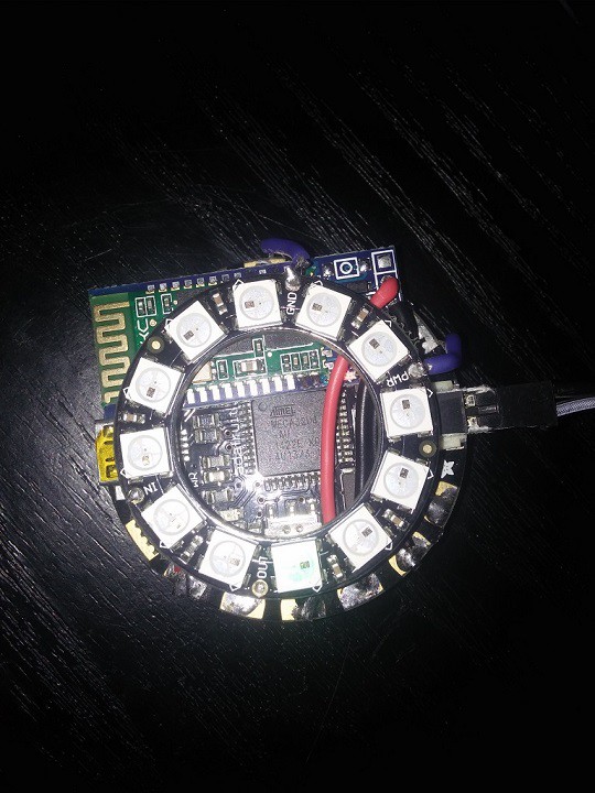
BT module sandwiched between the neopixel and Flora. I didn’t want to cover the 32u4 chip because of the heat issues I was still having at the time.
Finally, after over a month of waiting, my HC-06 bluetooth module came in from China. For once it truly was ‘plug and play’, using the Serial1 interface for data transmission over the tx/rx pins. There are a couple apps on the play store that allow you to use your phone as a bluetooth Serial interface and it took under 10 minutes to have my phone controlling various neopixel animations. BLE would have been even nicer, but for 4$ and almost no setup necessary, I can’t complain about the HC-06.
02/03/2015
Getting Started with Amarino
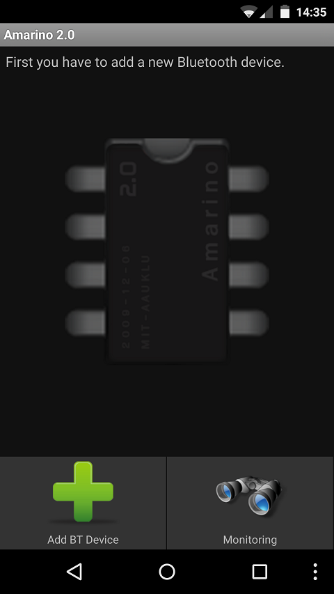
Amarino UI
The next step was to figure out how the data would be sent from my phone to the watch. Nothing available on the play store provided the functionality I needed, and it looked like I was going to have to write an app from scratch for my particular needs. Luckily, Amarino, (http://www.amarino-toolkit.net/index.php) an app created 4 years ago and probably not updated since, looked very promising. Through the use of plugins and the arduino library, it provides access to phone events. There are a couple plugins included that can send accelerometer data, incoming call status, etc. Developing plugins is also pretty easy, although a few modifications were necessary to migrate the 4 yr old plugin skeleton project to Android Studio. The Arduino library also took a little modifying so it worked with the Flora. Since you can have multiple plugins sending data at the same time, each receives a char flag. On the arduino side, the receiver function is running in the main loop, and data sent with a specific flag will trigger a corresponding function, and that function then processes the data array.
02/05/2015
Amarino Continued
My first objective was to have the neopixels display the time sent by my phone. To do this, I used the skeleton plugin project and Android calendar class to send h:m:s values to the Amarino app, which forwarded them to the arduino. Initially I only had the plugin send h:m values in 1 minute intervals, but found that the plugin would stop running. To solve this and increase the accuracy of the time from +/- 1 min to +/- 1s the time is now sent every second. Whether this has an impact on battery life is yet to be seen.
Sending phone notifications was more challenging to set up. I figured tasker can do a good job of reacting to phone notifications, and it’s much easier to edit notification actions than if it were coded in an app. The best way of implementing tasker into Amarino would have been by creating a tasker plugin, but my java skills are nearly non-existent. Instead, I am using tasker to broadcast intents over shell script. Figuring out how to do this and include the ‘extras’ needed for amarino to process the intents took forever, and involved a lot of trial and error. If anyone’s interested I can make a ‘how-to’ including the script tasker needs.
04/08/2015
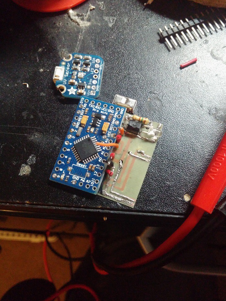
New Parts!
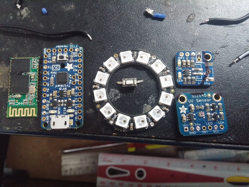
With my Flora still malfunctioning, I ordered a Trinket Pro and some other goodies. The Trinket Pro has a smaller form factor than the Flora, allowing the BT module to sit beside instead of on top of it. The main reason I went with the Trinket instead of an Arduino Pro Mini was due to it’s usb programming capabilities; necessary since I didn’t want to spend more money on an FTDI to USB cable. I also bought a SI1145 uv/visible/ir sensor. This communicates over I2C and allows the watch to have auto-brightness which is a feature I figured would make a huge difference when using the watch at night or outdoors. A photoresistor would have probably done the job too, but I was worried about it’s accuracy in low light. For a couple more bucks it’s cool to have UV and IR sensing capabilities as well. Lastly I bought an Adafruit battery backpack, allowing me to charge the Lipo over usb without unplugging it.
04/08/2015
Using Data Sent From Phone
The Amarino service is now properly set up to send data to the arduino, so now it’s time to use that data. The ‘meetAndroid’ library takes care of sending and receiving everything. Anytime data is received, the function corresponding to the associated flag is called. (Flag B in this case) To show the time, the hh:mm:ss value is sent in 1s intervals. It’s then just a matter of checking to see if the new value has an effect on the light position. (60min/5min intervals = 12 positions in hour/min mode) since redrawing the lights in 1s intervals causes flashing.
Notifications are received as single digit numbers with Flag A. A switch case specifies which neopixel animation function and what colour will be run. Right now I only have sms, snapchat, and gmail setup, however I added a few other animation colours so that if I want to send other notifications I only need to specify a different digit to be sent in the tasker shell script. After the animations run, the clock is redrawn. To show that there is still a pending notification, the clock is cleared on odd seconds and redrawn on even seconds (slow blink effect) until the phone screen is turned on.
Lastly, Incoming calls produce a ‘theaterchase’ effect that looks really cool. If the call is answered or stops ringing, the clock is redrawn.
04/09/2015
Adding More Functionality
Now that the main functionality is there, I wanted to add a couple more features that could be useful once in a while. The stopwatch function is pretty self explanatory; it starts a stopwatch at zero that can be paused, resumed, and reset. In order to show any second value (0-60) with only 12 leds, the led ring is numbered from 0-11. The seconds value is split into a first and second digit, which is shown on the watch with blue and green. (i.e 46s - blue on led 4, green on led 6)
To take advantage of the uv/ir/visible sensor, I added a uv meter that shows the current uv value, refreshed every 500ms, to 1 decimal. Indoors, it’s usually easy to pickup a value in the 0.1-0.5 range when close to a window. Outdoors the highest I have seen so far is 7.5.
Last is a simple flashlight function that makes the leds display white at full brightness. The current draw in this mode goes up from ~40ma to close to 200ma, but it’s much brighter and easier than constantly pulling out my phone to use the flash.
The menu system is pretty simple and there are only 2 accepted inputs: short click and long click. The picture below explains it quite well.
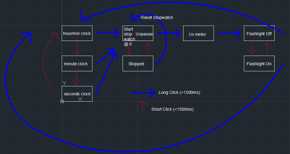
(Ugly) Function Tree
04/26/2015
Auto Brightness!
The neopixel leds are really really bright at full power. While this is great for readability outside, it quickly gets distracting indoors. Manually changing brightness with a sequence of button presses works but still requires me to interact with the watch whenever I step outside or the lights are turned off. With the SI1145 sensor I bought, I’m able to measure visible, ir, and uv light. I experimented with sampling visible and ir light in different environments to adjust the neopixel output brightness. Unfortunately, at low light levels the values can be a bit inconsistent. Visible light readings were especially bad, so I decided to use ir values for now. To filter out the inconsistencies I take the average of 5 readings. This repeats every 2 seconds. For some reason when I take more than 5 readings in a short period of time, the sensor stops working until the sketch is reset. Adding delays in the ‘for’ loop that read the values has no effect. Anyways, if the average value is greater or less than the range of values for the current brightness, the neopixels are redrawn with the new brightness level.
Lastly, I added an override for manual brightness control. Holding the button down for over 3 seconds toggles between low, high, and auto brightness. This is mostly for situations where the light level is such that the auto brightness keeps rapidly toggling the neopixel brightness.
04/26/2015
Putting it all together
Software-wise, nearly everything is completed. Now it comes down to making my wearable, well, wearable.
After some test fitting I decided that it would be better (for now) to have all the guts of the project tucked away, only leaving the neopixel and sensor on my wrist. Even with everything crammed together, it’s just too tall and wide to be one piece. Obviously this isn’t ideal, and I have a few better solutions once I can test it some more.
The sensor and neopixel connect to the rest of the components with a 7 pin cable normally used for balance charging 6s lipos. An added benefit of this is that it’s modular: I could theoretically unplug the neopixel and connect another module (gps, accelerometer etc) and I’ll already have all the pins I need (3.3v, raw V, GND, SDA, SCL, D6, D7) in place.
I quickly sketched an enclosure in autocad and cut it out of 3mm carbon fiber. It actually turned out a lot better than the hackjob I was expecting it to be.
Gallery:


04/26/2015
Custom PCB Design
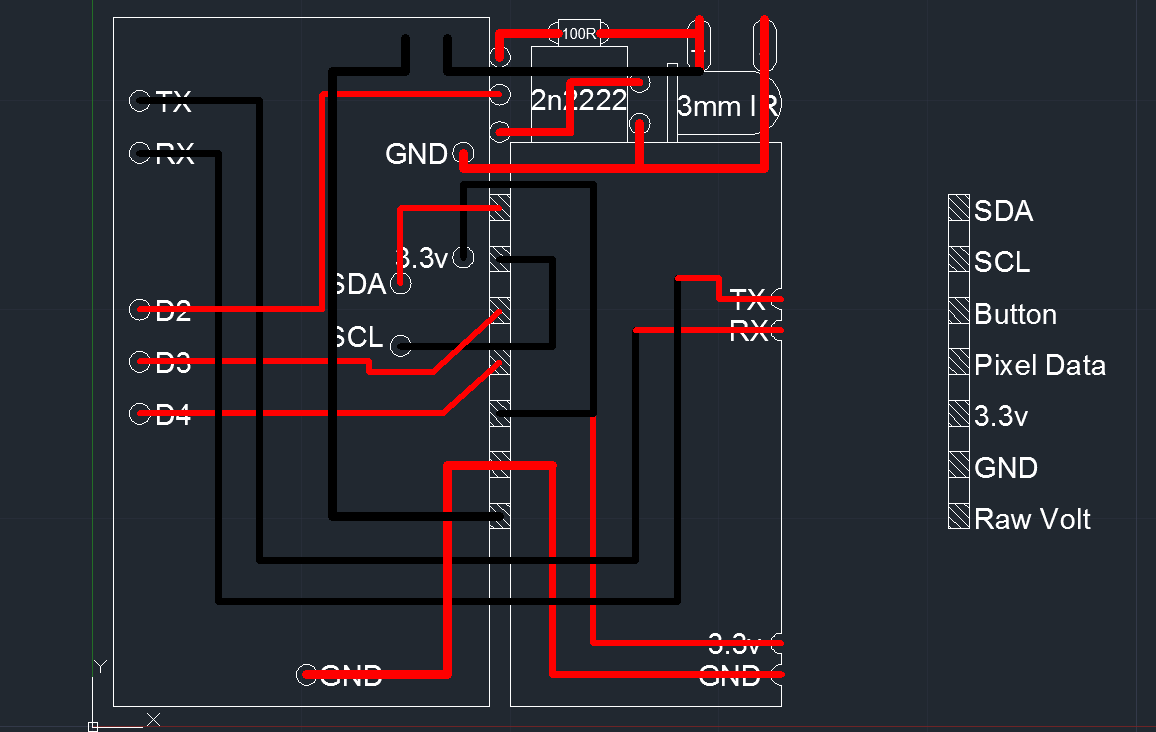
The current split design of the watch is a good test of the software, but could really use some improvements hardware-wise. My goal is to shrink down the footprint considerably and have the battery, circuit board(s) and neopixel ring as one piece on my wrist. The main challenge is to make the package thinner. To do this I’ve designed a circuit board that replaces all the messy wiring. Not only does this allow the watch to be thinner, but it also decreases the chance of wires being under tension and breaking. The design also incorporates tv-b-gone hardware in the top right corner which I thought was a cool addition. Since I’m not sending this to a board printing shop, I just used autoCAD to create a simple two sided design.
05/27/2015
Making the PCB
There are a few ways of making one-off pcbs, but I used the laser printer method. Hackaday actually has a really great tutorial for this here. On my first attempt I used parchment paper but it didn’t come off cleanly when ironed onto the copper clad board. I ended up using magazine paper; it doesn’t matter if it has print on it since only the laser toner is transferred onto the circuit board. With the iron I have, I had to press down for 5 minutes on each side for the toner to transfer cleanly. Next step was an HCL + H202 solution that etches away all remaining copper that isn’t covered by the toner. My finished product wasn’t perfect, so I tinned all the copper traces and checked with a multimeter to make sure all the connections were intact.
In my opinion, unless you need super low tolerances, the laser toner pcb etching method is a quick and easy solution for DIY projects.
01/08/2016
Problems, Problems, and more Problems
It’s been over half a year since my last post, and while this project has been consistently gaining followers, I’ve been struggling to bring it to an end. The first of the problems that I encountered involved the circuit board. A result of the mere 0.4mm thickness is that it is extremely flexible. While wearing or handling it, it’s easy to accidentally bend the board and have a solder joint break. In my two boards, I was able to completely assemble the first before noticing a bad connection, while I had to scrap the second one before even soldering on the neopixel ring. Finding the bad connection is nearly impossible after the whole stack of batery + pcb + arduino + lux sensor + neopixel ring are assembled and glued together. I considered reflowing the solder by sticking it in the oven (without the battery of course) but figured this had a bigger chance of damaging other components.
The other problem I had, and one that drove me absolutely insane, was trying to integrate tv-b-gone functionality into the watch. I followed adafruit’s tv-b-gone guide as closely as possible as the flora uses he same 32u4 chip as the trinket pro, albeit at a different clock speed. I played around with different resistors, voltages, ir leds, and nothing worked. Even Ken Shirriff’s excellent write-up on arduino pwm registers which goes in depth on how to use the internal timers to output pwm at any desired frequency wasn’t able to help me. I suspect it may have to do with the 12mhz clock speed. From what I understand, the tv codes that are stored in memory are scaled by the clock frequency when retrieved. With no real way to troubleshoot (it either turns off the tv, or it doesn’t) I’ve finally given up and will be using the space on the watch for a vibrator motor. Yes, it’s the easy way out, but at this point I need to finish the watch and this has been holding me up for far too long.
02/03/2016
Finishing up the Hardware
Well, the watch is finally finished on the hardware side. Spurred on by the new parts that had arrived, I dedicated a weekend to soldering and gluing everything together. Never underestimate the value of quality wire; 30awg silicone insulated wire made the job a million times easier than the old 26awg pvc crap I was using. I had initially planned a two piece design, with the arduino, battery, and BL receiver on the bottom of the wrist, and the sensor and light ring on top. Turns out I could mount everything as one piece without compromising thinness too much. The adafruit usb charger module sits off to the side and is covered by the strap when worn. Keeping track of the wires was difficult as they’re all black, and I nearly destroyed the arduino when I swapped the ground and 5v usb wires, but the end result looks really clean. The watch face comes from a 0.3mm sheet of carbon. It’s flexible enough that you can push down anywhere on the right side of the watch to trigger the button. I replaced the elastic band with a black fabric strap that complements the rest of the watch nicely.
Below are some pictures of the build: